Review Article - Volume 4 - Issue 2
Biomechanical evolution two types of TiO2 and AuNp implants after maxillofacial surgery
Ghazizadeh Elham1 2 3*; Zahra Naseri1
1Department of Bioinspired Materials and Biosensor Technologies, Institute of Materials Science, Faculty of Engineering, Kiel University, Germany.
2Radiation Sciences Department, Iran University of Medical Sciences (IUMS), Tehran, Iran.
3Department of medical biotechnology, Mashhad University of Medical Sciences, Mashhad, Iran.
Received Date : Feb 10, 2024
Accepted Date : Mar 06, 2024
Published Date: Mar 13, 2024
Copyright: © Elham G 2024
*Corresponding Author : Ghazizadeh Elham Department of Bioinspired Materials and Biosensor Technologies, Institute of Materials Science, Faculty of Engineering, Kiel University, Germany.
Email: elhamgenetic@yahoo.com
DOI: Doi.org/10.55920/2771-019X/1647
Abstract
In this study, we compare two different nanomaterials of dental implant materials from biomechanical properties in order to introduce a novel simulation method to choose the best materials for dental implants. Drilling process was performed in the cortical bone via finite element analysis simulation. The 3D model was derived of the produced hole of drilled site. So, we used as ITI design for dental implant model. We considered the change in the volume of the cortical bone around each implant to evaluating bone damage. For stability analysis, the micromotion of dental implant in the mandible after implantation was used. After implant loading, the volume changes in newly formed cortical bone around TiO2 and AuNP dental implants were measured at 0.010704 and 0.010886 mm3, respectively. Furthermore, micromotion of TiO2 and AuNP dental implants were measured at 0.00498 and 0.004838 mm, respectively. The bone volume ratio for TiO2 and AuNP was 80.3%, 32.3% and This study showed that TiO2 dental implant creates better conditions than AuNP dental implant in the maxillofacial region. However, the results of the studies are very close to each other and this closeness shows their nano-properties.
Keywords: Dental implant; Biomechanics; Drilling operation; Implant; nanomaterials.
Introduction
Implants can be offered as a suitable replacement for original teeth [1]. However, some drawbacks exist during and after implantation during the process due to the biological and physicochemical reasons [2,3]. There are some factors as bone degradation which it can occur due to surgical trauma or bacterial invasion. Failures in implantation can suggest that we should know the further information about stress‒strain distribution of implant stability [4]. Osseointegration was introduced as a mechanism in which host bone tissue biomechanically was placed as implant [5]. Many clinical researches indicated that failure implants were due bone attenuation or decay around the implant [6,7]. An approach, employment of mechanical loading on implants as newly formed bone around the implants, producing stress and strain in this region, which results in bone structure deformation [8]. It has some effective parameters with implants, prosthesis material, implant surface structure and property of bone‒implant interfaces which can significant roles in the transfer of force to implant‒bone interfaces [9,10]. Different materials like metals, ceramics and polymers are used to manufacture implants [11]. Recently, the practical use of nanomaterials has brought a new approach TiO2 nano tube arrays on the surface of dental implants were fabricated by two-step anodic oxidation [12]. The implants were classified into four groups is one of the metals used vastly for the manufacture of implants due to its stability, biocompatibility and mechanical properties. Additionally, some metallic alloys such as stainless steel, AuNP,Au, cd alloys are metals used to this end [13,14]. In this study, we examine the biomechanical evolution of TiO2 an AuNP as two types of nanomaterials on reconstructed area of cortical bone in the mandible with investigation by a practical test and calculation of percentage of bone formation after six weeks. After that, the effect of each implant on the general stability in newly grown cortical bone after 6 weeks was studied by finite element analysis.
Methods
In this research, we used as one practical and two simulation sections. In the practical section, we calculated of Young's modulus of newly grown cortical bone around two different implants after 6 weeks via on the percentage of bone formation. There were two section in simulation. In the first stage, the cortical bone of the jaw to achieve cavity geometry was drilling of and second the implantation and loading on it was happened by investigation of the parameters applied in this process.
The first section: Formation cortical bone around TiO2 and AuNP implants after 6 weeks and calculation of Young's modulus.
Calculation
We used as an in vivo animal model (a 2-year-old hybrid dog) was used for measuring the density of the newly formed bone. We separated the samples from the sacrificed dog's jaw after Six and calculated the percentages of the newly grown bone around the implants by histomorphometry. Then, the percentages of newly formed bone around TiO2 and AuNP implants were estimated at 38.9% and 36.4%, respectively. In the second part of this research, we supposed that the percentage of newly grown bone density around implants relative to 100% formed bone is equivalent to the values in the first part. This data is based on the fact which 100% formed cortical bone density was 2.1 g/cm [15] and its Young's mod- ulus was 12.8 GPa. The relation between the density and Young's modulus is shown in Equation 1[16].
E ̴ ρ3 -----Equation 1
By supposing 38.9% bone formation around TiO2 implant and 36.4%, around of AuNP implants implant, newly formed cortical bone density around them were 0.7985 and 0.6896 g/cm3, respectively. By using equation1and making a relation between the density values and Young's modulus of 100% bone forma- tion, Young's modulus of the newly grown bone around Ti and Zr-2.5%Nb implants were 0.844 and 0.781 GPa, respectively.
The second section: Bone drilling:
1) Modeling: We designed a 3D-model from the cortical bone of the mandible by Catia software. So, the desirable model was imported into Deform 3D software. This software supposes the thickness of the cortical bone of the mandible to be 2 mm, which has been measured for the end part of the mandible in a previous research (17). Modeling of the drill bit was done by Deform 3D part and the diameter of the designed drill bit for this simulation is 4.2 mm, the rotation speed is 500rpm and the feed rate is 50 mm/min.
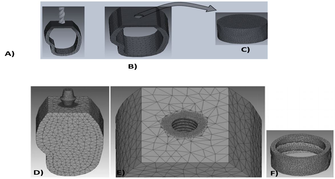
2) Determination of cortical bone material for drilling: We required stress‒strain curve of human cortical bone in various strain rates for cortical bone drilling. The relevant data were imported to Deform-3D software in Figure 1. Simulate drilling was shown that the state of cortical bone and drill bit model were supposed to be elastoplastic and rigid, respectively [18]. The number of elements relating to cortical bone model was 33217 and the number of nodes was 17896. In this model the size of meshes in drilled area was supposed to be 0.4 ≤ mm. We match the fix boundary condition which it was supposed for outer surfaces of jawbone model exceAuNP for the upper surface on which the drill bit. Boolean operation in Deform-3D software was used as the 3D design of the created in the second stage of the research (Figure 1(A,B)).
Implantation in the jawbone and applying load on implant:
1) Modeling: Drilled cortical bone model which the geometrically de rived models from the inside of the hole, obtained from the first part of simulation. We used as Catia software to design of the model of cancellous jawbone in maxilla and placed within the jaw cortical bone. An ITI standard implant (Institute Straumann AG, Waldenburg, Switzerland) with a diameter of 3.3 mm was designed by Catia software using data from a previous research [6]. The designed implant model was placed within the jawbone. Boolean operation in Deform-3D software were used to cutting the surface of the implant within the cancellous bone and also the geometric model was derived from the interior cavity form (Figure 1B). This figure shows the model of newly grown cortical bone around the implant. The diameter of the implant designed in this research was 4.2 mm, whereas the diameter of the cavity drilled in first part was 4.5 mm. The most important purpose of this study was to achieve a model of newly grown cortical bone around implant with a minimum thickness of 0.1 mm. In other words, the thickness of the newly formed bone around the thread tip of the implant was about 0.1 mm and between the threads it was about 0.3 mm.
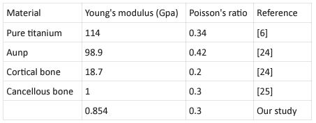
2) Nanomaterial determination: Loading simulation model was supposed to be implant nanomaterials were TiO2 and AuNP. Every data by Young's modulus and Poisson's ratio were modulated in Table 1. The size of elements in areas adjacent to implant and bone is approximately 0.1 mm which is smaller than other areas. The total numbers of elements for implant, drilled cortical bone, cancellous bone and newly grown cortical bone model were 58341, 27731, 54321 and 15467, respectively, and the numbers of nodes were 11016, 4608, 1354 and 37950, respectively. We were meshing them and specifying the suitable material for each one, the stick boundary condition was sup-posed for adjacent models. The upper surface of implants were applied by 100-N vertical. All the models entered into the Deform-3D software were in the STL format and all these simulations were performed in a system with 8192 MB RAM, Intel® Core™ i7-3770 CPU (Figure 1C,D).
Figure 1: A) Insertion of drill bit on the cortical bone; B) 3D geometry of the cavity by Boolean operation by the cavity created on the cortical bone.C) Created the novel capacity. D) Using the ITI implant model inserted into the jawbone; E) Extraction of implant geometry by Boolean operation; F) 3D software created the extraction of implant geometry from by Boolean operation.
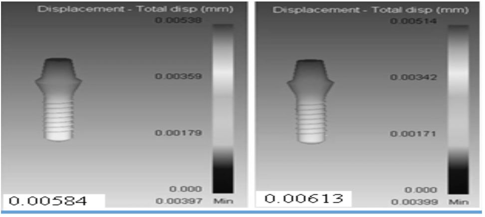
Figure 2: The schematic distribution of displacement in: A) of TiO2, B) AuNP implant after Maxillofacial Surgery.
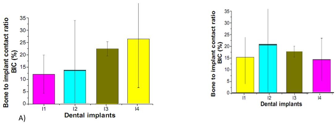
Figure 3: Bone-to-implant contact ratios of machined surface, surfaces, of A) TiO2 and B) AuNP Notes: (I1) machined surface implants TiO2 and and AuNP, (I2) surface implants, (I3) TiO2 and AuNP Nanotube array surface implants, and (I4) TiO2 nanotube array and AuNP surface implant.
Table 1: Mechanical properties of Nanomaterials related to our modulation.
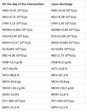
Table 1: The hematological examination on the day of the intervention and upon discharge of the patient.
Results and discussion
The volume changes in newly formed cortical bone model around each implant were calculated as a criterion to compare the bone defect around the implants, after these simulations. On the other hand, we estimated the displacement of each implant was measured as a criterion for stability of each implant in the jawbone. In relation to the first volume of newly grown cortical bone was measured at 3.68781 mm3 relate to volume change in the bone model around each implant. After application of 100-N vertical loading over two different implants, the volume of newly formed cortical bone TiO2 and AuNP dental implants were measured at 0.010704 and 0.010886 mm3, respectively. Furthermore, the maximum amount of displacement TiO2 and AuNP dental implants were 0.00613 and 0.00584 mm3, respectively (Figure 2). There was several research about different parameters related to implantation and their effect on the bone surrounding implants after loading. A study in this field evaluated the effect of different nanomaterials on emerged stress in cortical bone after loading the implant [16,17]. In that study, Lee et al1 proved osseointegration of dental titanium implants by TiO2 nanotube arrays with recombinant human bone morphogenetic protein-2[18]. In lee et al research was shown the effect of Pt@AuNPs by 3D printing materials which can refine the implant and enhance the sponge [19]. Our results have shown that the increasing effect of two nanomaterials (TiO2 and AuNP dental implants) in bone density which increases Young's modulus. Exactly, in the current study, two different types of materials were used for dental implants in order to investigate mechanical properties of implants and newly grown cortical bone around them. The results of the practical test 6 weeks after implantation showed that the cortical bone density around TiO2 implant was higher than that around AuNP. In other words, the rate of bone formation around the implant made of TiO2 is more than that formed around AuNP. In the next stage, the simulation of implant loading process was performed 6 weeks after implantation. The volume change in the surrounding bone was considered as a criterion to compare bone damage that each implant inflicted on its surrounding bone. The results showed that TiO2 implants resulted in less volume changes in the newly formed cortical bone around it in comparison with the AuNP. implants. In addition, the displacement of each im plant in the jawbone after loading was measured to investigate the stability of each implant in the bone (Table 1). Figure 3A, show the results of the histomorphometric analysis based on using TiO2 nanotube. The highest mean bone-to-implant contact ratio was found in the I4 group (39.5%), followed by the I3 group, I2 group, and I1 group (26.3%, 19.7%, and 10.1%, respectively). The bone volume ratios were measured around the implant threads. The highest bone volume ratio (89.3%) was also found in the I4 group, with values of 73.2%, 64.7%, and 53.9% in the I3 group, I2 group, and I1 group, respectively. These results suggest that the TiO2 nanotube array surface had more of an Osseo integration effect than the machined surface on the implant, and also had the biochemical effect of bone induction. Our findings concerning the effect of TiO2 nanotube arrays are similar to those of previous studies reporting an enhanced bone formation and cell adhesion effect with theTiO2 nanotube array implant. [20,21,22]. Bjursten et al12 reported that TiO2 nanotubes significantly improved bone bonding strength, bone-implant contact, and new bone formation when compared with titanium grit-blasted surfaces [23,24]. Because TiO2 nanotubes have a good oxide microstructure for growing new bone, TiO2 nanotube arrays are able to influence protein interactions and components of bone for rapid and permanent bone bonding. Figure 3B show the results of the histomorphometric analysis based on using TiO2 nano tube. The highest mean bone-to-implant contact ratio was found in the I2 group (80.3%) followed by the I3 group, I4 group, and I1 group (68.2%, 56.7%, and 48.9%, respectively). The bone volume ratios were measured around the implant threads. The highest bone volume ratio (32.5%), was also found in the I2 group, with values of 29.3%, 20.7%, and 18.1% in the I3 group, I4 group, and I1 group, respectively.Yassir et al show The aims of this study were to create a new surface topography using simulated body fluids (SBF) and Gold Nanoparticles (GNPs) and then to assess the influence of UV Photofunctionalization (PhF) on the osteogenic capacity of these surfaces [24]. Dong et al indicated that Titanium dental implants surface-immobilized with gold nanoparticles as osteoinductive agents for rapid osseointegration [25,26]. These results suggest that the TiO2 nanotube array surface had more of an osseointegration effect than the machined surface on the implant, and also had the biochemical effect of bone induction.
Conclusion
The results of the current study showed that using TiO2 dental implants not only inflicted less damage on the newly formed cortical bone but also resulted in higher stability in the surrounding bone tissue under loading compared to AuNP dental implants. The results of this study can help dentists select dental implantswith suitable materials. In addition, this research provided a novel simulation method to pre- dict the behavior of dental implants from biomechanical aspects for each material of dental implants.
References
- Guan H, Van Staden R, Loo Y-C, Johnson N, Ivanovski S, Meredith N. Influence of bone and dental implant parame- ters on stress distribution in the mandible: a finite element study. Int J Oral Maxillofac Implants. 2008; 24: 866-876. doi: 10.1007/s00707-010-0409-3.
- Lee C-C, Lin S-C, Kang M-J, Wu S-W, Fu P-Y. Effects of implant threads on the contact area and stress distribution of marginal bone. J Dent Sic. 2010; 5: 156-165. doi: 10.1016/s1991-7902(10)60023-2.
- VerriFR, de Souza Batista VE, Santiago JF, de Faria Al- meida DA, Pellizzer EP. Effect of crown-to-implant ratio on peri-implant stress: A finite element analysis. Mat SciEngC. 2014; 45: 234-240. doi: 10.1016/j.msec.2014.09.005.
- Baggi L, Cappelloni I, Di Girolamo M, Maceri F, Vairo G. The influence of implant diameter and length on stress dis- tribution of osseointegrated implants related to crestal bone geometry: a three-dimensional finite element analysis. J Prosthet Dent. 2008; 100: 422-431. doi: 10.1016/s0022- 3913(08)60259-0.
- Marcián P, Borák L, Valášek J, Kaiser J, Florian Z, Wolff J. Finite element analysis of dental implant loading on atroph- ic and non-atrophic cancellous and cortical mandibular bone–a feasibility study. J Biomech. 2014; 47: 3830-3836. doi: 10.1016/j.jbiomech.2014.10.019.
- Baggi L, Cappelloni I, Maceri F, Vairo G. Stress-based performance evaluation of osseointegrated dental implants by finite-element simulation.Simul Model PractTh. 2008; 16: 971-987. doi:10.1016/j.simpat.2008.05.009.
- Himmlova L, DostálováTj, Kácovský A , Konvic̆ ková S. Influence of implant length and diameter on stress distribu- tion: a finite element analysis. J Prosthet Dent. 2004; 91: 20- 25. doi: 10.1016/j.prosdent.2003.08.008.
- Rismanchian M, Birang R, Shahmoradi M, Talebi H, Zare RJ. Developing a new dental implant design and comparing its biomechanical features with four designs. Dent Res J. 2010; 7: 70. doi: 10.4103/1735-3327.92961.
- Chang CL, Chen CS, Huang CH, Hsu ML. Finite element analysis of the dental implant using a topology optimization method. Med Eng Phys. 2012; 34: 999-1008. doi: 10.1016/j.medengphy.2012.06.004.
- Osman RB, Swain MV. A critical review of dental implant materials with an emphasis on titanium versus zirconia. Ma- terials. 2015; 8: 932-958. doi: 10.3390/ma8030932.
- Li T, Hu K, Cheng L, et al. Optimum selection of the dental implant diameter and length in the posterior mandible with poor bone quality–A 3D finite element analysis. Appl Math Model. 2011; 35: 446-456. doi: 10.1016/j.apm.2010.07.008.
- Natali AN. Dental biomechanics: CRC Press. 2003. doi: 10.1201/9780203514849
- Schwartz-Dabney CL, Dechow PC. Edentulation Alters Ma- terial Properties of Cortical Bone in the Human Mandible. J Dent Res. 2002; 81: 613-617. doi: 10.1177/154405910208100907.
- Johnson T, Socrate S, Boyce M. A viscoelastic, viscoplastic model of cortical bone valid at low and high strain rates. Actabiomaterialia. 2010; 6: 4073-4080.doi: 10.1016/j.actbio.2010.04.017.
- Lughmani WA, Bouazza-Marouf K, Ashcroft I. Finite ele- ment modeling and experimentation of bone drilling forces.
- Webster RT, Albany TWC. Properties and Selection: Non- ferrous Alloys and Special-Purpose Materials. ASM Handbook. ASM International. 1990; 2: 9. doi: 10.1016/0142-1123(91)90190-a.
- Okumura N, Stegaroiu R, Kitamura E, Kurokawa K, Nomu- ra S. Influence of maxillary cortical bone thickness, implant design and implant diameter on stress around implants: a three-dimensional finite element analysis. J Prosthodont Res. 2010; 54: 133-142. doi: 10.1016/j.jpor.2009.12.004.
- Lee JK, Cho LR, Um HS, Chang BS, Cho KS. Bone formation and reodeling of three different dental implant surfaces with Escherichia coli-derived recombinant human bone morphogenetic protein 2 in a rabbit model. Int J Oral Maxillofac Implants. 2013; 28: 424-430.
- Lee SJ, Oh TJ, Bae TS, et al. Effect of bisphosphonates on anodized and heat-treated titanium surfaces: an animal experimental study. J Periodontol. 2011;82: 1035-1042.
- Bessho K, Carnes DL, Cavin R, Chen HY, Ong JL. BMP stimulation of bone response adjacent to titanium implants in vivo. Clin Oral Implants Res. 1999; 10: 212-218.
- Çalışkan N, Bayram C, Erdal E, Karahaliloğlu Z, Denkbaş EB. Titania nanotubes with adjustable dimensions for drug reservoir sites and enhanced cell adhesion. Mater Sci Eng C Mater Biol Appl. 2014; 35: 100-105.
- Bae IH, Yun KD, Kim HS, et al. Anodic oxidized nanotubular titanium implants enhance bone morphogenetic protein-2 delivery. J Biomed Mater Res B Appl Biomater. 2010; 93: 484-491.
- wikesjö UM, Qahash M, Polimeni G, et al. Alveolar ridge augmentation using implants coated with recombinant human bone morphogenetic protein-2: histologic observations. J Clin Periodontol. 2008; 35: 1001-1010.
- Park H, Kim w-R, Jeong H-T, et al. Fabrication of dye-sensitized solar cells by transplanting highly ordered TiO2nanotube arrays. Solar Energy Materials and Solar Cells. 2011; 95: 184-189.
- YassirElkhidirRenfaLaiZhiqiangFeng, The impact of photofunctionalized gold nanoparticles on osseointegration, Helion, Volume, Issue. 2018; 4(7): 00662.
- dong nyoung, HeoWan-Kyu Ko, Hak Rae Lee, Sang Jin Lee, Titanium dental implants surface-immobilized with gold nanoparticles as osteoinductive agents for rapid osseointegration, Journal of Colloid and Interface Science 469. 2016.

